Core Features:
C-ARM Camera Calibration
The first phase of this project involved determining the camera intrinsics of a C-arm machine, which is necessary for retrieving accurate camera positioning and orientation information. To achieve this, I designed a custom 3D fiducial marker, which was central to the calibration process. This design was inspired by a research paper that used 3D fiducials to determine intrinsics. The fiducial was 3D printed and incorporated stainless steel ball bearings, which were selected for their high visibility in X-ray imaging.
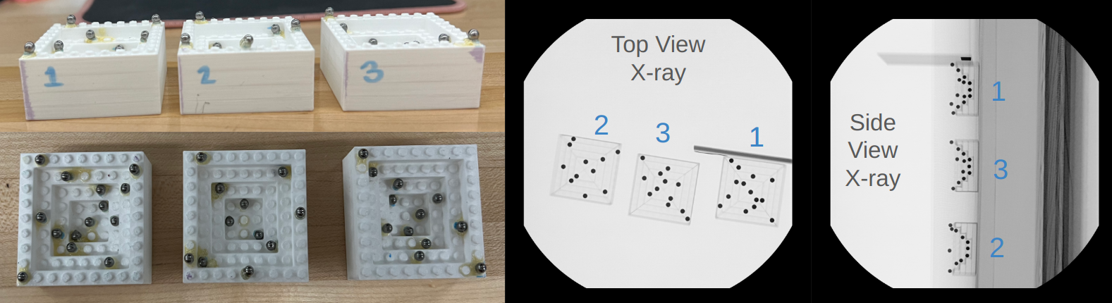
The three 3D fiducials used in the camera calibration process for the C-arm.
The next step was to calibrate the C-arm using this fiducial. The fiducial was placed in the imaging field of the C-arm, and several X-rays were captured (at least 10 from the top view and 10 from the side view). I utilized OpenCV to process the X-ray images and perform blob detection on the fiducial, which gave the center of each ball bearing. Once the centers of the ball bearings were identified, I established a 3D coordinate system for the fiducial marker, and then mapped the 2D positions of the detected centers in the X-ray image to this 3D coordinate system. Using OpenCV, I was then able to solve for the camera's intrinsic properties. The accuracy of these intrinsic parameters directly affects the accuracy of my trajectory generation.
Blob detection and coordinate mapping process. The process is the same for all fiducials.
Determining the Entry Point
The second phase of this project involved accurately determining the entry point for the spinal injection. To achieve this, I utilized an Intel RealSense camera to capture two images from different perspectives, each containing AprilTags. In the first image, two AprilTags are visible: Tag4, which has a known offset from the world frame, allowing me to establish a reference point in the world coordinate system, and Tag14, which provides additional spatial information necessary for triangulation.
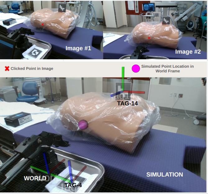
The two images used in determining the entry point. The X represents the desired entry point and the purple circle shows
location in simulated 3D space.
Using a stereo camera model, a technique that leverages two or more images taken from different angles to determine the 3D coordinates of points in a scene, I manually identified the same entry point in both images. These points were then projected from both images into a 3D point relative to the world frame.
Determining the Target Point Using X-ray Images
The third phase of this project involves accurately determining the target point within the patient's body, which is the final destination for the needle during the spinal injection. This step is crucial for ensuring the needle reaches the precise anatomical location intended. To determine the target point, two X-ray images taken at a 90° rotation from each other are used. A trained medical professional selects the target point in both images. This process uses the camera intrinsics determined in the first phase, ensuring that the transformations used are accurate. Central to this phase is the use of AprilTag 14. For this phase, Tag14 is attached to the fiducial marker, which allows for a known transform between the fiducial origin and the AprilTag, providing a reliable frame of reference for the calculations.
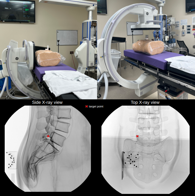
The two images used for determining the target point. The X represents the desired target point in each image. The photos are taken at 90° rotation from each
other.
A stereo camera model is again used to triangulate the two chosen points in the X-ray images into a 3D point in the Tag14 coordinate frame (P_tag14). Once P_tag14 is found, it can then be transformed to the world frame.
Determining the Trajectory
The final phase of this project involves determining the precise trajectory that the needle must follow to reach the target point previously identified. This is critical for ensuring that the needle enters at the correct orientation and travels the appropriate distance to reach the designated target. The needle angle and direction was calculated using the 3D coordinates of the entry and target points, both defined relative to the world frame. I calculated the straight-line distance between the entry point and the target point, which determines how far the needle must travel once it has been inserted into the body.
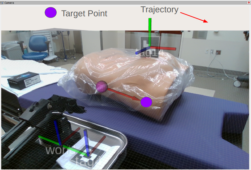
Simulation showing the trajectory calculated from the entry and target points.
It should be noted that
there is some error in the target point (and therefore trajectory), which is likely due to
imperfect camera calibration.
Finally, the robot will execute the movement, going to the entry point with its gripper aligned in the correct orientation.
Robot moving to entry location with gripper oriented at trajectory angle.